Consumer Electronics Injection Molding at Production Scale
Consumer electronics lives and dies on appearance and fit. For product and engineering teams, the question is whether a molder can deliver a flawless cosmetic surface and a tight, repeatable fit at volume — because a sink mark or a gap at the seam is visible to the end user on day one. That consistency is what separates a component supplier from a brand-quality partner.
An electronics molding program is a closed loop of resin and color control, tool polish, thin-wall process, and verification. When those elements are managed together, the part looks identical to the approved sample on every shipment. When they are managed separately, color drift, flash, and cosmetic defects appear and drive scrap and returns.
What the Capability Numbers Mean for Your Program
Specifications define the envelope in which electronics molding is predictable. A 50-ton to 400-ton press range covers small connectors through enclosures without oversizing the process. Tolerances of ±0.02 mm on critical features describe the envelope in which fit and sealing are controlled rather than heroic.
Mold life rated at 500,000 to 1,000,000 shots is a maintenance plan, not a sales figure. Tools are serviced by shot count so wear on cosmetic surfaces never surprises a shipment. Tooling lead time of 20 to 40 days reflects the added discipline of polished steel and validated color, and an annual capacity above 50,000,000 parts signals a floor built for sustained electronics volume.
How an Electronics Program Runs
Every electronics program at the Dongguan facility follows a disciplined path, and each step has an owner and a record:
- Design for manufacturability (DFM). Wall thickness, draft, gating, and cosmetic surfaces are reviewed so the part fills cleanly and looks flawless.
- Tool fabrication. The mold is machined from selected steel with high polish and validated on a tryout press with first-article data.
- Color and resin control. Resin is dried, color-matched, and conditioned so lot-to-lot color drift is controlled from the start.
- Molding. Molten thermoplastic is injected, packed, and cooled with thin-wall control and cavity-pressure monitoring.
- Ejection and handling. The part is removed by robot and routed with minimal handling to protect cosmetic surfaces.
- Verification. Critical dimensions and cosmetic criteria are checked with gauges and sampling; results are recorded.
The point of this structure is brand consistency. It is what lets your incoming inspection confirm rather than discover a defect.
Choosing the Right Resin
Material choice drives appearance, precision, and cost more than any other decision in electronics molding. The table below maps common thermoplastics to properties that matter.
| Resin | Key properties | Typical electronics applications |
|---|---|---|
| PC | Clarity, impact, heat | Enclosures, lenses |
| PC/ABS | Balance of impact and finish | Housings, bezels |
| ABS | Cost, surface, paintability | Shells, keypads |
| PBT | Dimensional stability, insulation | Connectors, terminals |
| LCP | Flow, stability, thin walls | High-density connectors |
| TPU | Soft-touch, sealing | Grips, gaskets |
Selection is matched to function, environment, and regulatory needs. For flame-retardant or low-leachable grades, the specific lot is qualified and documented from the first run.
Equipment and Plant Capacity
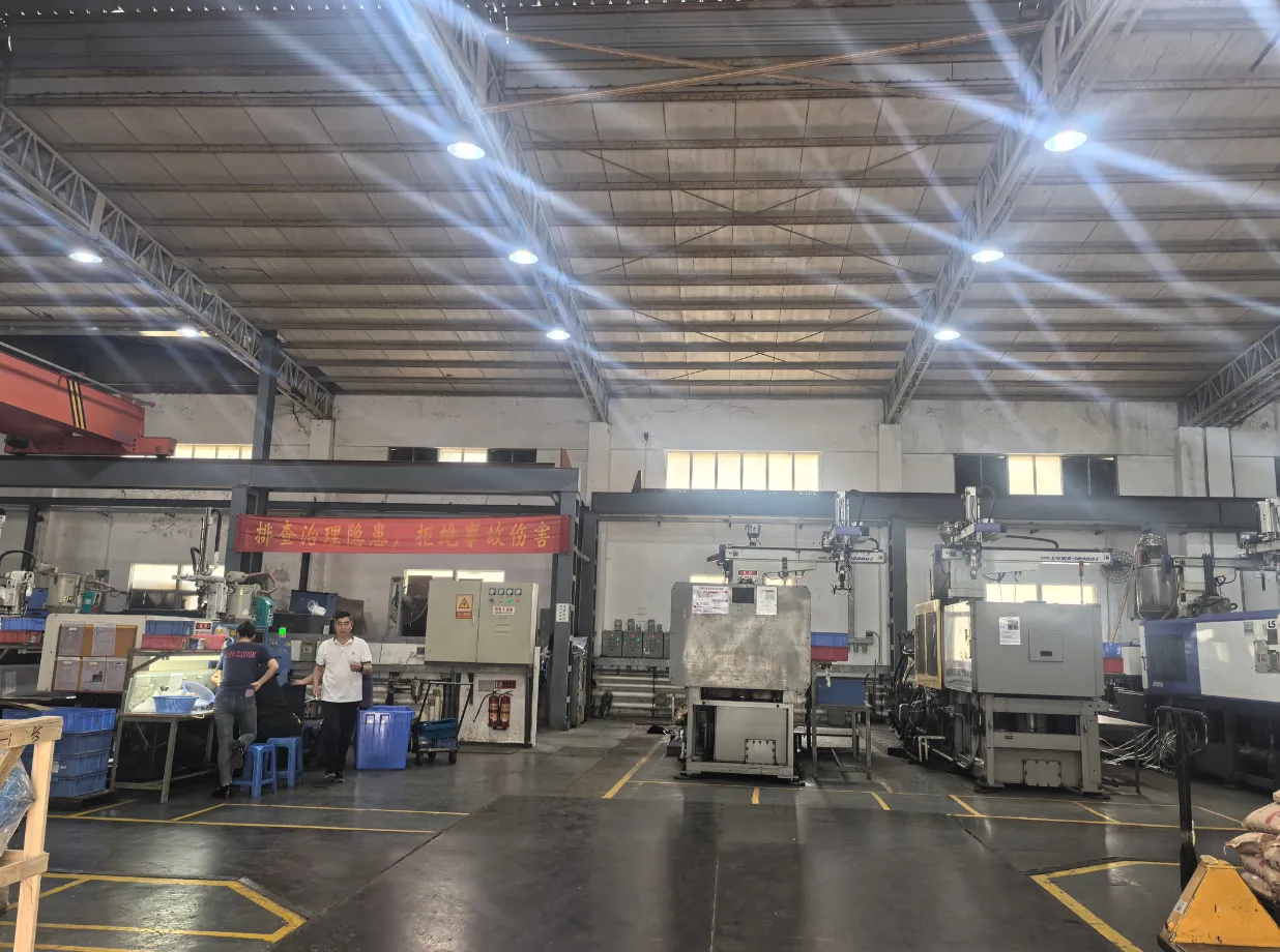
The Dongguan molding floor runs small high-speed presses with closed-loop control and cavity-pressure monitoring for electronics.
The plant runs computerized machines from 50T to 400T with closed-loop control and cavity-pressure monitoring. Dehumidifying dryers, central material handling, and conditioned resin keep process and color stable across long runs. Robotic part removal and careful handling protect cosmetic surfaces, and in-mold sensing with SPC charting catches drift before it becomes scrap.
Applications and Where They Fail
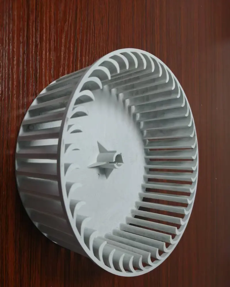
Electronics components where surface and dimensional precision determine field reliability.
Electronics molding appears wherever a part must look perfect and fit tightly in volume. Each application carries its own failure mode, and process controls are tuned to the requirement rather than applied generically:
- Device enclosures and housings — cosmetic surface and seam fit dominate.
- Connectors and terminals — dimensional precision and insulation are non-negotiable.
- Cosmetic shells and bezels — gloss, texture, and color consistency matter.
- Buttons and keypads — feel, travel, and appearance balance.
- Wearables and accessories — thin-wall and soft-touch drive design.
For electronics and medical programs, components are produced from qualified, often flame-retardant resins under controlled process discipline, where a single cosmetic or dimensional defect can trigger returns.
Quality and Compliance Expectations
Quality is engineered, not inspected in at the end. The facility operates under an ISO 9001 quality management system with documented controls at every step: incoming material verification, first-article inspection, in-process SPC, and final audit against the approved drawing. Dimensional verification uses CMM and calibrated gauges, with critical characteristics tracked lot by lot. For regulated industries, records and traceability are retained, and customer-specific protocols are supported where required.
Cost and Lead-Time Drivers
Buyers often fixate on piece price, but the total cost of an electronics molding program is set earlier and elsewhere:
- Tool steel and cavitation — polished multi-cavity tools cost more; the right balance depends on volume.
- Resin grade — flame-retardant and specialty grades cost more and mold differently.
- Tolerance and finish — high-gloss and ±0.02 mm add process and polishing cost.
- Secondary operations — printing, decoration, and assembly add handling but can lower landed cost versus multiple suppliers.
- Volume and cadence — steady runs amortize setup and stabilize pricing.
Lead time is dominated by validated tooling, not molding. A well-run DFM and a tool shop in the same building compress the critical path from design release to first article.
Common Defects and How They Are Prevented
Sink marks, flow lines, flash, short shots, and color drift are symptoms of process ignorance or weak color control, not bad luck. They are prevented by understanding how melt temperature, injection speed, packing pressure, and cooling time interact for each resin family — and by validating those settings on a tryout press before a production commit. Cavity-pressure monitoring and color management confirm every shot is in spec, and SPC charts flag drift before it becomes scrap.
Related Capabilities
Electronics molding is one option in a broader toolkit. Pair it with Precision Injection Molding for tight-tolerance parts, Two-shot Injection Molding for multi-color shells, or Insert Molding for metal-plastic connectors. See the homepage for the full capability overview.